Load Cell
Load Cell terminal block is an input specific for load cells. It has a high-resolution amplifier specialized to amplify this type of sensor. The gain is fixed and is adapted to load cells of 2mV/V and 3mV/V at full range.
Load Cell
Load cells are force sensors. In their application for dynamometers they are mounted on the dynamometer so that the torque applied to it can be measured.
Depending on the type of dynamometer, 200Kg, 500Kg or 1000Kg cells are supplied. Although it is also possible to use other types of 4-wire load cells or resistive bridge type sensors.
Mechanical assembly of the cell
In cases where the load cell is not pre-installed by the dyno manufacturer, the load cell must be mounted in a similar way as indicated in this figure.
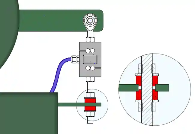
Consider the following:
-
The distance from the cell to the center of the dynamometer will depend on the range of the cell and the capacity of the dynamometer.
Calculation: Minimum Load Cell Distance = Max Dyno Torque / Max Load Cell Force
Example, in a dynamometer with 100 Kgm max torque, with a 200 Kg range load cell, distance should be 0.50 m or greater (> 500 mm).
-
Mount the load cell on rubber cushioning (red color in the figure). This will prevent the system from measuring vibrations and will also preserve the useful life of the load cell since vibrations damage it in the long term.
- The load cell can be mounted to work in both tension and compression, but a tension mount is preferable, since compression mounting must be much more precise in its alignment.
- Rubbers can be mounted on both ends of the load cell, but rubber can also be mounted on one side and a ball joint on the other side, which helps to be more forgiving with alignment.
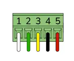
Load Cell Input Pinout
| Number | Function | Color | Range |
|---|---|---|---|
| 1 | Signal(+) | White | Load Cell Signal + |
| 2 | Signal(-) | Green | Load Cell Signal - |
| 3 | GND | Yellow | 0V |
| 4 | EXC(-) | Black | -V |
| 5 | EXC(+) | Red | +V |
| Number | Function | Color | Range |
|---|---|---|---|
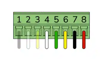
| 1 | Signal | Black | RPM2 Input |
| 2 | GND | Yellow | 0V RPM2 |
| 3 | VCC | White | +5V RPM2 |
| 4 | Signal(+) | White | Load Cell Signal+ |
| 5 | Signal(-) | Green | Load Cell Signal - |
| 6 | GND | Yellow | 0V |
| 7 | EXC(-) | Black | Load Cell Excitation V- |
| 8 | EXC(+) | Red | +V |
Load Cell signals enters throug signal #9 in Accudyno software.
Calibration
Load cells have some tolerance between different units of the same model and brand, so it is not possible to replace one load cell with another directly, but it is necessary to perform a calibration procedure.
The software has a calibration method that is adapted to dynamometers. Calibration is performed by generating a weight or torque on the dynamometer with the help of weights of known value.