RPM2
The RPM2 input can be used to input the engine RPM using a dedicated sensor (not included) or it can be used to input the signal from a second inertial chassis dyno in the case of all wheel drive dynos. In case of using AWD mode, the connection will be identical to the main roller dyno sensor in RPM1.
Why don´t you include an engine RPM sensor?
The main reason is that for normal use it is a sensor that is not essential to work on the dyno, since it is only needed during RPM synchronization. An external tachometer or the vehicle's own tachometer can be used.
The other reason why we do not include an engine sensor is the great variety of engine types that our users work with: injection automotive engines, external or integrated to the spark plug coils, older ignitions, magneto ignitions with or without CDI , etc. This problem makes it impossible for us to build a universal sensor that works with all these ignition types, or it would be very expensive to do so.
We know that having an engine RPM sensor is very useful for synchronizing or detecting certain problems such as roller slippage. That's why we include some possible ways to input the signal to the system.
RPM2 Input Pinout

| Number | Function | Range | Signal in Software |
|---|---|---|---|
| 1 | VDC | +5V for sensor | |
| 2 | GND | 0V | |
| 3 | Signal | Digital input with 2K pullup | 12 |
| 4 | N/C | No Connection | - |
Pulses per revolution: software programmable.
Sensor Type
We are going to try to provide information so that those who need, can build their own engine RPM sensor.
Direct Input from ECU
It is possible to take a direct signal from the ECU, as long as it is a clean 5V signal. The system allows to adapt the pulses per revolution in the software configuration.
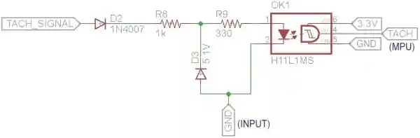
Coil Primary
The coil primary current pulse has voltages in the hundreds of volts that are harmful if fed directly into Accudyno input. There are modules to adapt this signal safely by means of an optocoupler.
These two circuits are similar and the advantage is that they are optocoupled, so it is quite safe not to damage either the Accudyno interface or the PC.
Motorcycles
This circuit cannot be used to measure RPM on 2T or 4T motors running on magneto power supply, as it draws too much current, loads the supply coil too much and causes the motor to fail.
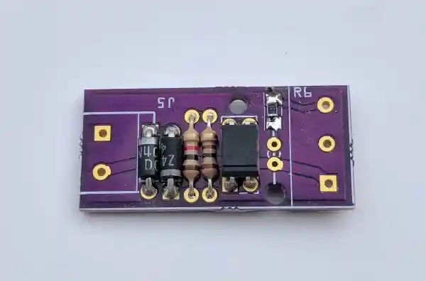
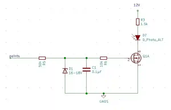
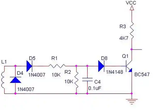
Inductive Clamp
This circuit senses by induction and triggers a signal on the output transistor. It can be used with an inductive clamp.
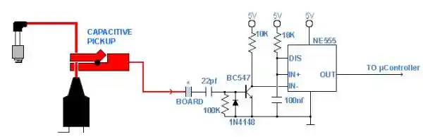
Capacitive Clamp
This circuit has a capacitive coupling input and triggers a signal on the output transistor. It can be used with a capacitive clamp or capacitive coupling by means of a simple cable near the spark plug cable. We haven't tested it but it probably works even by injecting the transistor signal to the Accudyno input, without the need for the NE555 timer.