Front panel
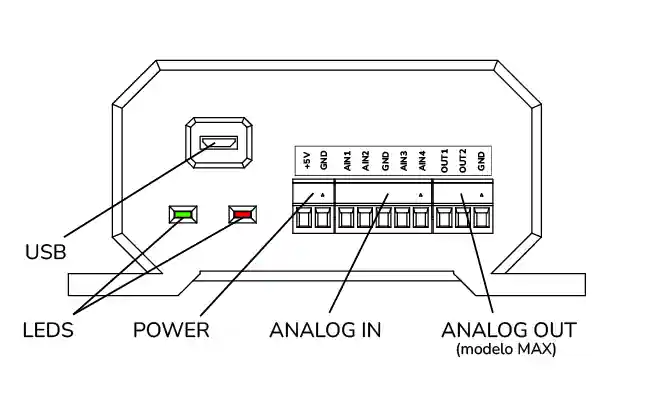
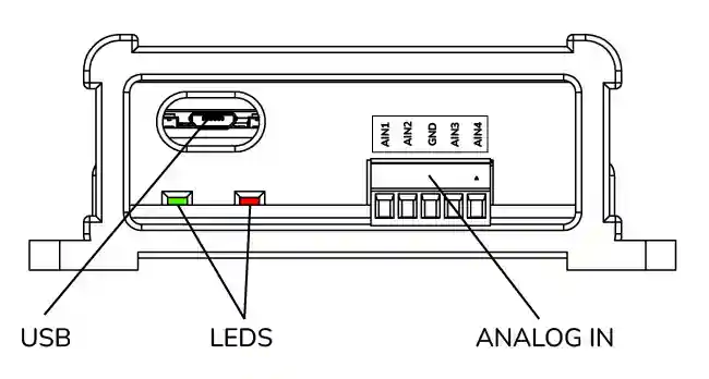
USB input
Connect the supplied Micro USB cable here and the other end to the PC. The USB cable should not be longer than 3m. Always use good quality USB cables. If you require a longer length, you must use amplified USB cables (available in 10 or 15m lengths).
Keep the USB cable away from sources of interference, such as 12V motor cables, motor or pump cables, ignition cables, spark plug cables, solenoid valve or brake relay cables.
LEDs
Red and Green LEDs are used as indication of current state. Red LED indicates error and green led shows current state.
| Red LED | Green LED | State |
|---|---|---|
| Flashing | Off | No connection |
| Off | Blinking | Connected |
| Blinking | Flashing | Retrying Wifi connection |
| Flashing | Blinking | Wifi connected |
| Blinking | Off | Wifi connection failed |
Sensor Testing
This function can be used to test the rotation sensor or to adjust the distance between the sensor and the magnet.
Power
Auxiliary terminal block with access to 5V (from the supply USB port) and to GND. It can be used to power a sensor. This terminal block can also be used to supply 5V to the module if you don't want to use the microUSB input or more voltage precision is required.
AIN: Analog Inputs
Four analog inputs. The lambda probe is typically connected here. Pressure sensors or NTC temperature sensors can also be connected int these inputs.
OUT: Analog Outputs
Analog outputs to control a fan or some other device. Only available in model "Gyra MAX". The output can be configured to supply either a voltage or a PWM output signal.